Finite Element Analysis
Home Finite Element Analysis Force Tolerance Surface Finish Regression

OPTIMUM DESIGN AND MACHINING PARAMETERS OF A PERMANENT MAGNET BRUSHLESS DC LINEAR MOTOR AS A CNC FEED DRIVE

By

William Tereshkovich

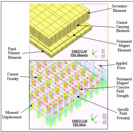
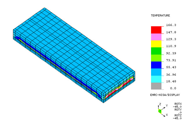
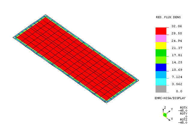
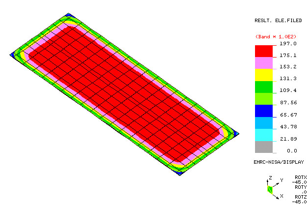
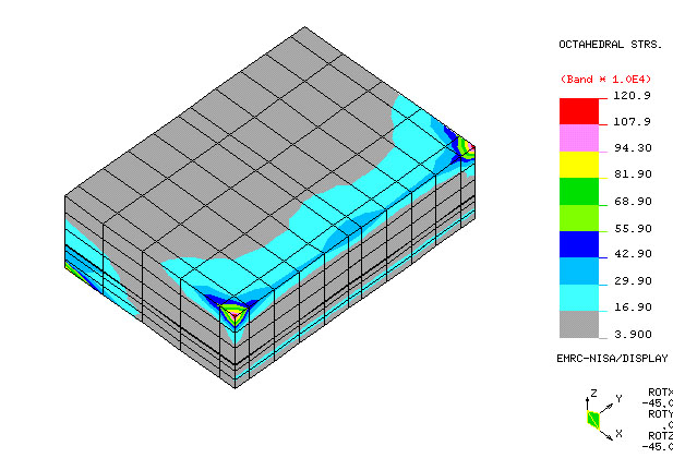
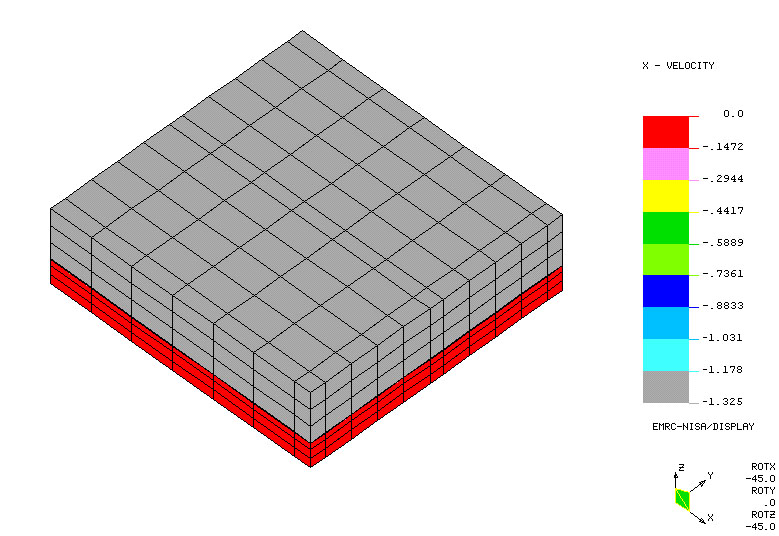
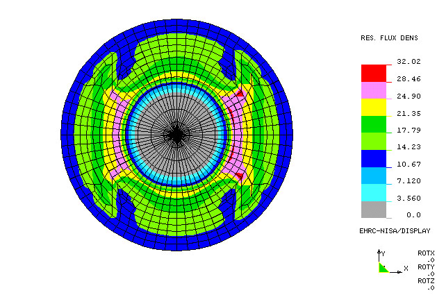
Graphical Output     Simulation    Output Files

Finite Element Analysis Graphical Output

Figure 1 PMBDCLM FEA Mesh and Boundary Conditions
Figure 2 PMBDCLM Magneto-Thermal Analysis
Figure 3 PMBDCLM Resultant Flux Density, Air-Gap Elements
Figure 4 PMBDCLM Resultant Electric Field, Air-Gap Elements
Figure 5 PMBDCLM Octahedral Stress, Quarter Model
Figure 6 PMBDCLM Slider Velocity, Quarter Model
Figure 7 DC Servomotor Resultant Flux Density

Finite Element Analysis Animation

Simulation 1 (AVI) PMBDCLM Magneto-Thermal Analysis, Complete Model (1)
Simulation 2 (AVI) PMBDCLM Magneto-Thermal Analysis, Complete Model (2)
Simulation 3 (AVI) PMBDCLM Magneto-Thermal Analysis, Magnet Array & Primary Elements
Simulation 4 (AVI) PMBDCLM Magneto-Thermal Analysis, Rotation and Complete Views
Simulation 5 (AVI) PMBDCLM Complete Magneto-Thermal Analysis
Simulation 6 (AVI) PMBDCLM Primary and Secondary SXX Stress
Simulation 7 (AVI) PMBDCLM Primary and Secondary SYY Stress
Simulation 8 (AVI) PMBDCLM Velocity and Guideway Stress (1)
Simulation 9 (AVI) PMBDCLM Velocity and Guideway Stress (2)
Simulation 10 (AVI) PMBDCLM Velocity and Guideway Stress (3)
Simulation 11 (AVI) PMBDCLM Primary and Secondary Guideway SXX Stress/Velocity (1)
Simulation 12 (AVI) PMBDCLM Primary and Secondary Guideway SXY Stress/Velocity (2)
Simulation 13 (AVI) PMBDCLM Primary and Secondary Guideway SXY Stress/Velocity (3)
Simulation 14 (AVI) PMBDCLM Primary and Secondary Guideway SXY Stress/Velocity (3)       

Sample Finite Element OUTPUT Files

Magneto-Thermal Analysis (Output)
Magnetic Field Analysis (Output)
Electric Field Analysis (Output)
Static Analysis (Output)
Dynamic Analysis (Output)

                                                                                                            Back to Top of Page